Configure WSPR
Use this page for WSPR station identity, transmission planning, frequency, power reporting, and calibration. Return to the Signal Setup overview to choose another mode. For calibration procedures, see Transmission Timing and Calibration; for output hardware, see Configure Transmitter.
WSPR or Weak Signal Propagation Reporting is the original mode for Wsprry Pi.
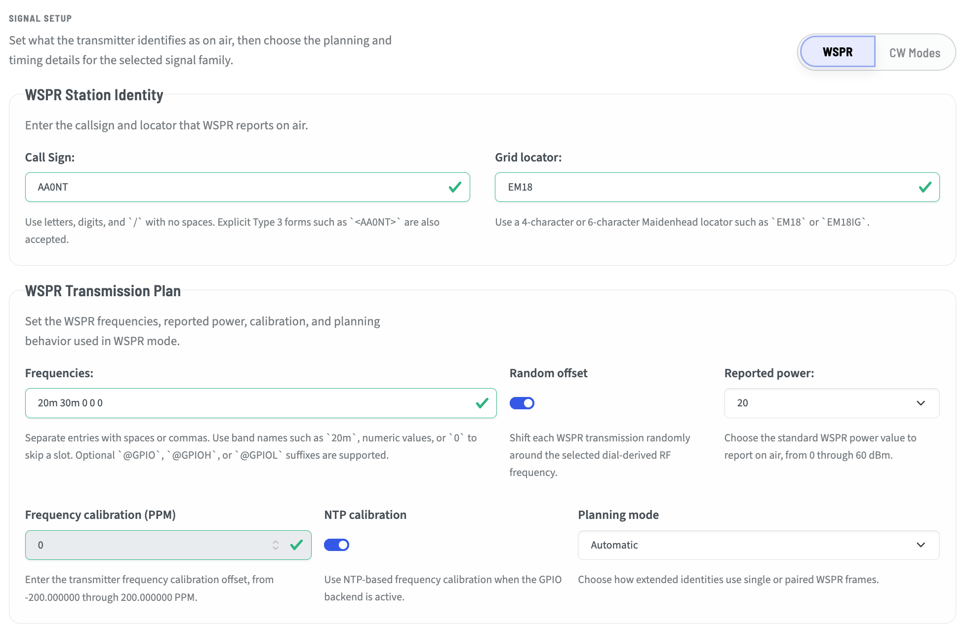
Station Identity
Within the Station identity section, you will set your callsign and locator. For normal Type 1 WSPR messages, the callsign is any valid 6-character or fewer. The Grid Locator is the four- character Maidenhead locator for where you are transmitting.
If you need or desire to use callsign extensions, have a callsign longer than 6 characters, or want or need to use a six-character locator, you will need to consider using Type 2 or 3 messages.
WSPR Transmission Type Selection Examples
Callsign |
Locator |
Meaning |
Allowed/Required Transmission |
|---|---|---|---|
|
|
Standard callsign with 4-character locator |
Type 1 single-frame |
|
|
Standard callsign with 6-character locator |
Type 1/3 paired transmission should be used if full 6-character locator reporting is required |
|
|
Explicit Type 3 callsign with 4-character locator |
Not useful; Type 3 is intended for extended locator or hashed callsign use |
|
|
Explicit Type 3 callsign with 6-character locator |
Type 1/3 paired transmission |
|
|
Compound/prefixed callsign with 4-character locator |
Type 2 single-frame |
|
|
Compound/prefixed callsign with 6-character locator |
Type 2/3 paired transmission |
|
|
Explicit Type 3 form of compound/prefixed callsign |
Type 2/3 paired transmission |
|
|
Compound/suffixed callsign with 4-character locator |
Type 2 single-frame |
|
|
Compound/suffixed callsign with 6-character locator |
Type 2/3 paired transmission |
|
|
Explicit Type 3 form of compound/suffixed callsign |
Type 2/3 paired transmission |
Rule Summary
A normal callsign with a 4-character locator uses Type 1.
AA0NT EM18
A normal callsign with a 6-character locator requires a Type 1/3 pair to remain self-identifying.
AA0NT EM18
<AA0NT> EM18IG
A compound, portable, or prefixed callsign with a 4-character locator uses Type 2.
W0/AA0NT EM18
AA0NT/P EM18
A compound, portable, or prefixed callsign with a 6-character locator requires a Type 2/3 pair.
W0/AA0NT EM18
<W0/AA0NT> EM18IG
AA0NT/P EM18
<AA0NT/P> EM18IG
Angle brackets request an explicit Type 3 callsign frame.
<AA0NT>
This should not make pairing invalid. Instead, when paired transmission is required, the planner should choose the appropriate companion frame:
Standard inner callsign: Type 1/3 pair
Compound inner callsign: Type 2/3 pair
WSPR Transmission Plan
These settings govern the way that WSPR is transmitted or received.
Frequencies
The Frequencies setting is a single frequency, or a list of frequencies, separated by spaces or commas. The frequencies may be in band format:
10m
20m
30m
etc.
They may also be listed in engineering notation where these are all the same:
50MHz
0.05GHz
50000kHz
50000000Hz
Notice that there are no spaces between the number and m for meters, and none between the number and the engineering notation.
Finally, the frequency may be listed in pure Hz without a notation such as 21096.100.
Of note, WSPR is an Upper Side Band (USB) mode. The frequency entered is a typical USB dial frequency. You may note that the tones are shifted ~1,500Hz higher.
Using the bands will select the canonical WSPR frequency.
Random offset
Turning this switch on will add a positive or negative random offset to the transmitted frequency. This can be handy when there is a lot of traffic on WSPR, and allow you to find a more clear slice of the available bandwidth.
Reported Power
Reported power is not the same as the actual transmission power. The transmitters settings may be attenuated by the LPF and additional gain may be added. Possible values are:
0, 3, 7, 10, 13, 17, 20, 23, 27, 30, 33, 37, 40, 43, 47, 50, 53, 57, 60
dBm is added to the encoder WSPR message to be a reference for the decoded message. The operator should choose the value that is closest to their actual transmission power.
This setting has no bearing on actual transmission power.
Frequency calibration (PPM) & NTP Calibration
Some operators may choose to manually calibrate their rig. This is more important with GPIO-based transmissions where the Raspberry Pi frequencies may be impacted by power, heat, and mechanical differences.
Others may opt for the simpler and “accurate enough” NTP calibration. This uses an internet time source to calibrate the output frequency. For most bands, this is more than reasonable. Some operators on higher bands such as 6m and 2m may find even a small deviation puts them out of the transmission boundaries, and may need to use a calculated PPM adjustment.
When NTP is enabled, the Frequency Calibration field is dithered. When using the Si5351 clock module, NTP is disabled and manual calibration should be used - although the combination of a TCXO and the Si5351 is often so close, it may be ignored.
In all cases, NTP will continue to keep the Pi in sync to time messages appropriately.
Planning Mode
Planning mode relates to the use of Type 1, 2, and 3 messages, and the behavior when certain data elements are entered.
Automatic - The planner attempts to choose the best transmission plan based on the data entered.
Prefer paired when available - If the planner finds it can generate both Type 2 and 3 messages, it will do so in alternating windows.
Require paired - Requires the planner to always use a paired Type 2 and 3 message format. For those who want the additional data to be received and understood by even the most remote stations under challenging conditions, this is likely the best choice.